Sliding Mode Control of an Octarotor for Fault Tolerant Control
Nonlinear sliding mode controller for an octarotor that maintains stable flight under single and dual rotor failures by exploiting actuator redundancy
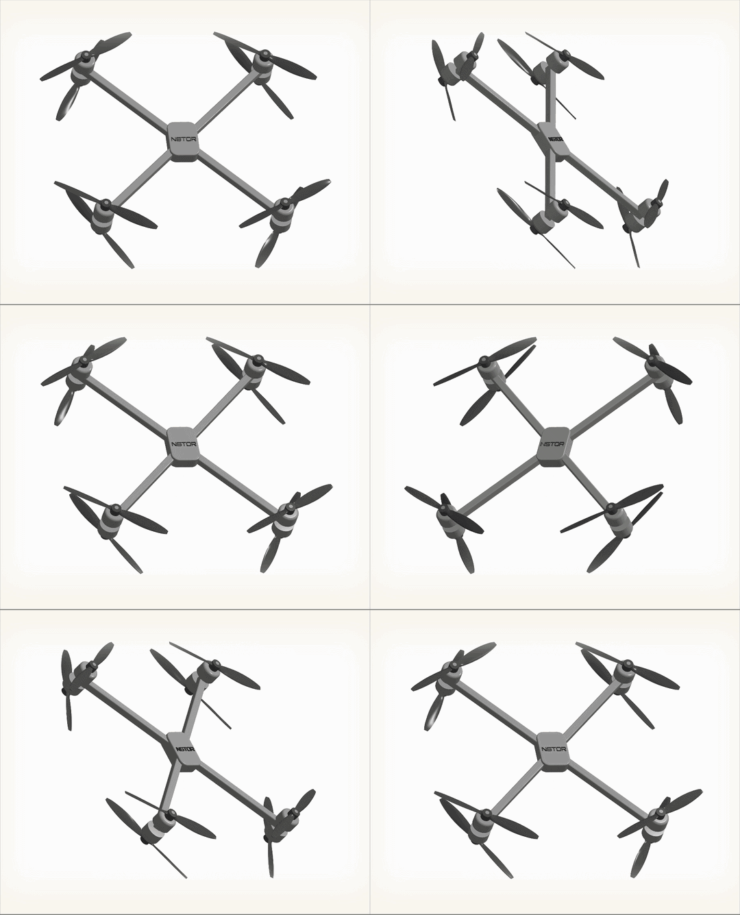
A nonlinear sliding mode controller designed for an octarotor multirotor that maintains stable trajectory tracking under single and dual rotor failures. The octarotor’s actuator redundancy (8 rotors, 4 controlled DOF) is exploited through real-time control reallocation, while the sliding mode law provides robustness against matched uncertainty without requiring a precise fault magnitude estimate.
Octarotor Configuration
An octarotor has 8 rotors arranged symmetrically, producing an overdetermined mapping from rotor thrusts to body forces and moments. This redundancy is the key to fault tolerance: when one or more rotors fail, the remaining rotors can still span the required wrench space.
| Parameter | Value |
|---|---|
| Number of rotors | 8 |
| Configuration | X8 coaxial / flat octo |
| Controlled DOF | 4 (\(F_z\), \(\tau_\phi\), \(\tau_\theta\), \(\tau_\psi\)) |
| Max simultaneous failures tolerated | 2 (configuration dependent) |
Vehicle Dynamics
The full 6-DOF rigid body dynamics follow the Newton-Euler equations expressed in the inertial frame:
\[m\ddot{p} = F_g + R\,f_T\] \[J\dot{\omega} = -\omega \times J\omega + \tau\] \[\dot{\eta} = W(\eta)\,\omega\]where \(p \in \mathbb{R}^3\) is position, \(R \in SO(3)\) is the rotation matrix from body to inertial frame, \(\eta = [\phi,\,\theta,\,\psi]^\top\) are roll-pitch-yaw Euler angles, \(\omega \in \mathbb{R}^3\) is the body angular rate, \(J\) is the inertia matrix, and \(W(\eta)\) is the kinematic transformation matrix:
\[W(\eta) = \begin{bmatrix} 1 & \sin\phi\tan\theta & \cos\phi\tan\theta \\ 0 & \cos\phi & -\sin\phi \\ 0 & \sin\phi\sec\theta & \cos\phi\sec\theta \end{bmatrix}\]Actuator Fault Model
Each rotor \(i\) is assigned an effectiveness factor \(\gamma_i \in [0,\,1]\), where \(\gamma_i = 1\) is fully healthy and \(\gamma_i = 0\) is a complete failure. The effective thrust of rotor \(i\) is:
\[T_i^{\text{eff}} = \gamma_i\,k_T\,\Omega_i^2\]Collecting all eight rotors, the fault matrix is:
\[\Gamma = \text{diag}(\gamma_1,\,\gamma_2,\,\ldots,\,\gamma_8) \in \mathbb{R}^{8\times 8}\]The total wrench produced by the vehicle is:
\[\begin{bmatrix} F_z \\ \tau_\phi \\ \tau_\theta \\ \tau_\psi \end{bmatrix} = \underbrace{B\,\Gamma}_{B_\Gamma} \begin{bmatrix} \Omega_1^2 \\ \vdots \\ \Omega_8^2 \end{bmatrix}\]where \(B \in \mathbb{R}^{4\times 8}\) is the geometric mixing matrix. Under a fault, the effective mixing matrix becomes \(B_\Gamma = B\Gamma\).
Sliding Mode Control
Sliding Surfaces
Define position error \(e_p = p - p_{\text{ref}}\) and attitude error \(e_\eta = \eta - \eta_{\text{ref}}\). The sliding surfaces are chosen as first-order linear surfaces:
\[s_p = \dot{e}_p + \Lambda_p\,e_p \in \mathbb{R}^3\] \[s_\eta = \dot{e}_\eta + \Lambda_\eta\,e_\eta \in \mathbb{R}^3\]where \(\Lambda_p,\,\Lambda_\eta > 0\) are diagonal gain matrices that determine the closed-loop dynamics on the surface.
Equivalent and Switching Control
The total control law is composed of an equivalent term (drives the state to the surface) and a switching term (holds it there):
\[u = u_{\text{eq}} + u_{\text{sw}}\]The equivalent control is derived by setting \(\dot{s} = 0\) and solving for the input that would maintain the state on the surface in the absence of uncertainty:
\[u_{\text{eq}} = B_\Gamma^{+}\left(\ddot{x}_{\text{ref}} - \Lambda\,\dot{e} + f(x)\right)\]where \(B_\Gamma^+ = B_\Gamma^\top(B_\Gamma B_\Gamma^\top)^{-1}\) is the Moore-Penrose pseudoinverse of the faulted mixing matrix and \(f(x)\) captures known nonlinear terms (gravity, Coriolis).
The switching control rejects matched disturbances and uncertainty:
\[u_{\text{sw}} = -K\,\text{sgn}(s)\]with gain matrix \(K > \|\delta\|_\infty\,I\) where \(\delta\) bounds the matched uncertainty.
Reaching Condition
With Lyapunov candidate \(V = \frac{1}{2}s^\top s \geq 0\), the reaching condition requires:
\[\dot{V} = s^\top \dot{s} \leq -\eta_0\|s\|_1 < 0 \quad \forall\; s \neq 0\]This guarantees the state trajectory reaches the sliding surface in finite time and remains there thereafter. Substituting the control law:
\[\dot{V} = s^\top\bigl[\dot{e}_{\text{dynamics}} - u_{\text{eq}} - K\,\text{sgn}(s)\bigr] \leq s^\top\delta - K\|s\|_1 \leq \bigl(\|\delta\| - K\bigr)\|s\|_1\]Setting \(K > \|\delta\|\) ensures \(\dot{V} < 0\).
Chattering Reduction
The discontinuous signum function causes high-frequency chattering in physical actuators. This is replaced with a continuous boundary layer saturation:
\[\text{sat}\!\left(\frac{s_i}{\phi}\right) = \begin{cases} \text{sgn}(s_i) & |s_i| > \phi \\ \dfrac{s_i}{\phi} & |s_i| \leq \phi \end{cases}\]Inside the boundary layer of thickness \(\phi > 0\), the controller acts as a linear PD law; outside it switches. This introduces a small steady-state error but eliminates actuator wear from high-frequency switching.
Control Allocation Under Faults
With the faulted effective mixing matrix \(B_\Gamma\), the control allocation solves the minimum-norm problem:
\[u^* = \arg\min_{u \geq 0} \|u\|^2 \quad \text{subject to} \quad B_\Gamma\,u = \nu_{\text{des}}\]where \(\nu_{\text{des}} = [F_{z,\text{des}},\,\tau_{\phi,\text{des}},\,\tau_{\theta,\text{des}},\,\tau_{\psi,\text{des}}]^\top\) is the virtual control demanded by the SMC outer loop. The solution via pseudoinverse is:
\[u^* = B_\Gamma^+\,\nu_{\text{des}}\]The octarotor’s redundancy ensures \(B_\Gamma\) retains full row rank (rank 4) even after losing one or two rotors in most geometric configurations, meaning \(B_\Gamma^+\) exists and the desired wrench remains achievable.
Fault Tolerance Analysis
The null space of \(B_\Gamma\) has dimension \(8 - \text{rank}(B_\Gamma)\). For a healthy vehicle, \(\text{rank}(B) = 4\) and the null space has dimension 4 — four free directions that do no net work. After a failure (\(\gamma_i = 0\)), effective rank can drop only if the lost rotor was geometrically critical. For a symmetric flat octarotor:
| Failure scenario | Rank of \(B_\Gamma\) | Controllable |
|---|---|---|
| 0 failures | 4 | Yes |
| 1 failure (any rotor) | 4 | Yes |
| 2 adjacent failures | 4 | Yes |
| 2 opposite failures | 3 | Partial (yaw authority lost) |
| 3+ failures | \(\leq 3\) | Degraded |
Stability on the Sliding Surface
Once the state reaches the surface (\(s = 0\)), the sliding mode dynamics reduce to:
\[\dot{e} + \Lambda\,e = 0 \implies e(t) = e(0)\,e^{-\Lambda t}\]This is globally exponentially stable with time constant \(\tau = 1/\lambda_{\min}(\Lambda)\). The sliding mode controller thus guarantees:
- Finite-time reaching of the sliding surface
- Exponential convergence of tracking error to zero on the surface
- Robustness to any matched disturbance bounded by the switching gain \(K\)
Implementation
def sliding_mode_control(state, ref, Gamma, gains):
    e_p  = state.pos  - ref.pos
    e_v  = state.vel  - ref.vel
    e_eta = state.eta - ref.eta
    e_om  = state.omega - ref.omega

    # Sliding surfaces
    s_p   = e_v  + gains.lam_p  * e_p
    s_eta = e_om + gains.lam_eta * e_eta

    # Effective mixing matrix under fault
    B_eff    = B @ Gamma
    B_eff_pinv = np.linalg.pinv(B_eff)

    # Equivalent + switching control
    nu_eq  = ref.acc - gains.lam_p * e_v + g_vec
    nu_sw  = -gains.K * sat(np.concatenate([s_p, s_eta]), phi=gains.phi)
    nu_des = nu_eq + nu_sw

    # Minimum-norm rotor allocation
    u_star = B_eff_pinv @ nu_des
    return np.clip(u_star, 0, Omega_max**2)